You've got an APC system in you SAAB (I hope). But what is it? and how does it work? and Is it possible to use it on other cars?
Well read on and see... and we'll now explain the function and parts of the APC set-up.
If you got questions that aren't answered below please visit the APC forum
TOC
1. Q&A
2. General Information
3. Normal function
4. Trouble shooting the APC-system
5. APC components (time line)
6. Included parts
7. Circuit diagrams
Q&A
(quick info about the APC)
Writer: Widde
Q: What does APC stand for?
A: Automatic Performance Control
Q: What does the APC do?
A: The APC controls the boost pressure. If "knock" occurs the APC
lowers the boost pressure to a safe level. The boost follows the RPM.
Q: How does the APC control the boost?
A: The APC controls a APC valve, which controls the flow of air to the Waste gate. With this
set-up, the APC makes it possible to increase the boost from
the "base boost pressure" to the ordinary boost pressure by
"bleeding" some of the air from the waste gate.
Q: What is "base boost pressure"?
A: The "base boost pressure" is the level of boost pressure when the waste gate
opens. "Base boost pressure" can be achieved when the
high-comp side of the turbo is connected directly to the waste gate (this is the
standard way of doing a turbo application without any boost control except for
the waste gate).
Q: How does the APC know when to open/close the APC valve to control the boost?
A: The APC does not just open and close the valve. The APC oscillates the valve
at aprox 12 Hz over a specific RPM value. and then alters the duty cycle of the
open and close pulse to send more or less air to the waste gate.
Q: So the APC sets a boost value above the "base boost" and then just
holds it there. Why couldn't the base boost pressure always be the higher boost
value? Why is the APC needed in that case?
A: The answer for that is, Fuel quality. In a high boost turbo application the
quality of the fuel is very important. If you got low-grade fuel, the boost
pressure must be lower to minimize "knock". If you got high-grade fuel
the boost can be higher and more power could be produced and there would be no
knock. APC controls the boost pressure so no knock should occur. If knock occurs
the APC will lower the boost to ensure the safety of the engine. So the APC will
adjust the boost pressure to the maximum power outtake for the fuel you are
running on.
Q: How does the APC sense knock?
A: On the engine block there is a knock sensor mounted. The sensor works like a
microphone, which listens for "knock".
Q: How does the APC know what boost I'm running on?
A: To the intake manifold a pressure sensor is connected. This sensor is feeding
the APC control unit the boost level.
Q: How do I set the boost pressure?
A: The "boost level" is set by the "F" pot inside the APC control unit
The "base boost" is set by the waste gate
Q: So if I I just turn the "F" pot all the way, then I will get more
power?
A: Yes and No, you might increase the boost setting but due to other parameters
that would not be enough. For example, fuel quality, fuel pressure, APC rise
rate, etc.
Q: What about the other pot-s K&P?
A: The K-pot is the "knock" sensitivity setting, this shall never be
altered unless you are an expert.
The P-pot is the "rise rate" of the boost level
Q: What's the "Rise Rate" vs. the "boost level"
A: The "boost level" is the wanted level that the boost pressure
should stay.
The "rise rate" is how fast the APC control unit
should try to reach the "boost level"
Q: Then I just maximize the "rise rate" to get the "boost
level" up ASAP.
A: It's not that simple! If you set the "rise rate" to low. Then it
will take too long for the "boost level" to reach the wanted level.
And if you set the "rise rate" too high the "boost level"
will overshoot the wanted "boost level" and this can seriously damage
the engine.
Q: Can I recalibrate the "knock" sensitivity.
A: On a SAAB should this not be necessary! The K-pot should never ever be
touched, If you do not know what you are getting into.
Q: How do I see if "knock" occurs?
A. It is not possible on a stock APC controller to see that. You may notice that
the boost is lowered. But you can build a monitor LED with the help of the
internal APC controller knock monitor and mount the LED on the dashboard.
Q: How do I use the internal "knock" monitor function in the APC controller?
A: You will need a ordinary LED and connect it to pin 19 on the APC controller connector. The pin will be "drawn to zero" (grounded) when the APC
controller indicates "knock". Inside the APC controller there are
resistors connected in serial with this function, so just connect the anode of
the LED to +12v and the cathode of the LED to pin 19 with some wires and you
should be set.
Q: What about runaway boost pressure?
A: Also included in the APC system there is a pressure guard that will cut the
power to the fuel pump if the boost rises over a specific level. In high boost
application the pressure guard must be recalibrated to a higher boost setting.
Some people just bypasses the pressure guard with a wire. I would not recommend
that. It's better to have a pressure guard just in case. I hope that I does not
need to explain why.
Q: How do I set the higher boost cut level on the pressure guard?
A: You will need to turn the larger "screw" on the pressure guard
"clockwise" (in) 1-1,5 turn. On a stock pressure guard this will rise
the boost cut level to circa 1.3 bar. Do not touch the other smaller
"screws"
Q: Is the APC system always activated?
A: Yes and No. The APC controller is powered up when the engine is running. But
the APC valve will be disconnected when you apply the brake and sometimes
when the cruise control activates/deactivates.
Q: I want to "Left brake" with full boost, how do I do that?
A: You will need to bypass the APC valve brake switch with a
wire.
Q: How does it all fit together?
A: look at the picture below, and use the included parts list below to work it
out.
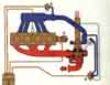
Picture borrowed with
permission from Jan
1. Knock sensor
2. APC control unit
3. Pressure sensor
4. APC valve
5. Distributor (RPM signal)
Q: Can I use the SAAB APC system on an other car?
A: I can't see why not! the only trick is the calibration of the
"knock" detection. Otherwise it should be a bolt on.
General
information
Writer: Anders Olsson, translated by: Widde
APC Automatic Performance Control
was developed by SAAB in the beginning of the 1980 due to the problem of poor
fuel quality in the turbo cars. The problems lead to knock and often severe
engine damages.
The APC-system is a relative simple electronic control system which listens for
knock in the engine and controls the boost pressure so that knock won't appear.
The APC-system made it possible to remove the previous engine safety margins
that were build into the engine to minimize the knock. The compression could be
raised from 7,2:1 to 8.5:1 which led to better torque at low RPM and better fuel
economy.
The APC-system consists of an analogue ECU which with information from boost
pressure, vibrations from the engine block and the RPM of the engine controls
the boost pressure. The boost pressure is controlled through electric
pulses to a valve which controls the pressure to the waste gate. This leads
to control of the boost pressure.
The APC-system got two
major duties:
1. Regulating the boost pressure according to a predetermined algorithm, the
boost pressure follows the RPM of the engine.
2. If knock occurs, immediately lower the boost pressure so knock stops.
The ECU (APC-box) is a completely analogue unit that through amplify, filter and
comparing the input signals will calculate a output signal to the APC-valve.
The APC-box gets
information about the current boost pressure by the pressure sensor. The
pressure sensor got a one hose connection and two electrical connectors. The
sensor consists of a wire winded resistor, a spring based membrane and a
mechanical device that holds the together the membrane with a connector which
moves over the resistor.
The resistance between the sensors two connectors will rise when the boost
pressure rises.
@ 0 bar relative (atmospheric pressure) or lower, the resistance is aprox 10 Ohm
@ 0.8 bar relative, the resistance is aprox 100 Ohm
The APC-box gets information
about the engine vibrations through the knock sensor. The sensor consist of a
piezoelectric crystal.
The crystal will transmit a electric current when it is exposed to pressure
forces. The crystal is encased in a protective casing and is bolted to the
engine block, under the intake manifold.
The crystal, and thus the knock sensor output signal is depending on how much
the crystal is forced together.
Because of the pressure applied through the bolt, it's really important that the
torque is absolutely correct.
When the engine vibrates the crystal will vibrate and thus be exposed to varied
pressure forces, which will give a electric signal that corresponds with the
engine vibrations.
The APC-box get the RPM info from the "ignition pulse amplifier".
The Output signal from
the APC-Box is sent to the APC valve.
The valve got three hose connections and two electric connectors.
The three hose connections is connected like this:
W - Wastegate (the wastegate actuator)
C - Compressor (Turbo compressor housing or the throttle body)
R - Return (before the turbo, between the AMM and the turbo inlet)
There's a choke in the
C-connector to limit the airflow trough the valve.
Between the two electrical connectors is a solenoid attached. When the APC-box sends
current to the valve, a magnetic field is generated in the solenoid. The
magnetic field lifts a spring based valve that opens the R-connector and permits
air to flow to the R-connection.
The boost pressure is controlled by the APC-box which opens and closes the valve
with different intervals. Thus the pressure which controls the wastegate can be
varied.
The pulses got a fixed frequency at 12 Hz. 12 times open and 12 times closed
every second.
At low RPM and Low boost pressures the APC will order maximum boost pressure.
The valve will have a continuous current flowing through it and due to this the
valve will be quiet.
The APC-box filters the
signal from the knock sensor to get the part of the signal that shows abnormal
engine vibrations, which are knock. This signal will be amplified and is the compared
with a predetermined value to determine if the knock level is acceptable or not.
If knock occurs the the valve will be immediately disconnected from the signal
to ensure fast boost pressure drop.
As long as the knock occurs the APC will lower the boost pressure. The longer
the knock the lower the boost pressure. When the knock stops, the APC will stop
lower the boost pressure and stabilize the pressure at this level. After a
second the APC will slowly try to rise the boost pressure. If knock occurs again
the APC will lower the boost pressure and the sequence will repeat it selves.
Within the APC, a safety function is included. This function will disconnect the valve if the knock sensor doesn't work. This function listens to the knock sensor signal to check for normal engine noise. If the signal from the knock sensor is to faint the APC interprets it as a knock sensor failure and disconnects the valve. This function will only be active over 2300 RPMs.
The signal from the
pressure sensor and the RPM signal is decoded in by APC. The APC got a
predetermined boost pressure algorithm built in, which make the APC lower the
boost pressure when the RPM rises. Depending on different versions of APC-boxes
the boost pressure will be lowered differently on high RPMs.
So it's a built in function of the APC thet lowers the boost on high RPMs.
On the newer implementations of the APC-systems (dual row connector), there's a
function that will disconnect the valve when the brake is applied.
On newer cars with a
cruise control there's a switch connected to the ground of the valve, that will
disconnect the valve when the cruise control is active.
There's an extra safety system that protects the engine against high boosts,
just in case if the wastegate actuator is faulty or if the hose to the wastegate
actuator will loosen. This system is completely separated from the APC-system an
consists of a pressure guard which is connected to the fuel pump relay. If the
boost pressure rises past a certain level the pressure guard will disconnect the
fuel pump and the engine will stop until the boost pressure has been lowered
below the cut off level.
Fuel-cut levels, pressure guard:
T8(140-155hp) = 0.95+-0.05 bar
T16(175-185hp) = 1.10+-0.05 bar
Normal
Function
Writer: Anders Olsson, translated by: Widde
Assuming the engine is
in good condition, the ignition is calibrated correctly, the fuel mixture as it
should and the gasoline is of a good octane rate. Then should a stock APC act
like this:
- when the engine is shut off the boost gauge needle should be in between the
white and the yellow field.
- at idle the needle should be in the white field of the boost gauge
- at full throttle from low RPM the needle should rise from to the border
between the yellow and the red field and the slowly go back towards the white
all together with a rising RPM
- APC lowers the boost at High RPM. Different APC ECUs lowers the boost
different. Normally will the needle stay in the yellow field some mm from the
red border @ 5000 RPM
- during heavy load, for example: full throttle at low RPM going uphill, then
the needle could momentarily enter the red field, but shouldn't stay there for a
longer time.
If fuel with a low
octane rate is used or if any other fault generates knock. Then should a stock APC act
like this:
- When the needle nears the red field knock could in some cases appear.
- APC will detects the knock and lowers the boost immediately.
- Sometimes could the knock be heard by the human ear, but only sometimes.
- The needle will at knock suddenly jump down some millimetres
- When the knock has ended the boost will slowly rise again and eventually knock
will occur again and the boost level will drop again.
- The states "knock" -> "boost lowering" -> "no
knock" -> "boost rise" -> etc will take aprox. 3-5 seconds
and will appear as the boost pressure and acceleration is slowly pulsating.
Troubleshooting the APC-system
Writer: Anders Olsson, translated by: Widde
If the APC-system does not work according the "Normal Function" you can troubleshoot it
fairly simple.
This guide assumes the following:
- Engine is free from any mechanical errors
- ALL vacuum hoses and ALL hoses between the air filter and intake manifold are controlled
thoroughly for leaks
- The APC-box is not modified. If the box is modified the descriptions about how high the APC gauge shall rise at max.
Troubleshooting process if the APC gauge doesn't rise over the middle of the yellow
field:
1. turn on the ignition (the headlights should now be activated), but do not start the engine. open the bonnet.
If the APC-valve is "chattering" all the time, it means that the APC believes one of the following:
- Turbo boost over 0.4 Bar
- Engine is "knocking"
- RPM is over 2300 RPM
none of these alternatives shall be present if the engine is off, so the APC must get wrong information.
Most probable cause is that the APC believes that the boost is high, even though that is not the case.
The pressure sensor, which gives info about the boost pressure, uses a resistance value that increases with increased boost pressure. If a breakage occurs in the
circuit the resistance becomes "infinite" which leads to that the APC believes the boost is "infinite" and thus trying to decrease the boost pressure.
De most probable cause is a faulty Pressure sensor.
Start by checking the pressure giver and the cables.
If the pressure sensor is ok, then the fault might reside within the APC box. Try to exchange to another APC-box.
2. Try to disconnect and reconnect the APC-valve electrical connector.
There shall be a "click" from APC-valve when the connector is removed and inserted.
If this procedure is repeted a few times the APC-valve might chatter a few seconds after the connector is inserted.
This depends on that the APC-box has became "unstable" and this is normal.
If the APC-valve does not "click", check the following:
- fuse to the APC-system is not broken
- The connector to the APC-box is fastened
- On cars with the new APC-box (25 pin), verify that the brake light does not shine
- The connector on the APC-valve is not corroded/oxidised
- Resistance through the APC-valve should be aprox 27 ohm
- That it is not possible to "blow" through the APC-valve "R"
connector whilst the APC-valve is disconnected
If the fault remains, check and clean the electrical connectors attached to the ground point
on the radiator beam.
Measure then following:
- +12 & ground to the APC-box
- ground to the APC-valve
- verify the cable from the APC-box to the APC-valve
If the fault can't be found try to exchange the APC-box.
If it's possible to "blow" through the APC-valves "R connector. Then the valve is broken and needs to be replaced.
3. Test-drive the car with the APC-valve disconnected (base-boost)
The APC-gauge shall rise to the middle of the yellow field.
If the APC-gauge stays in the beginning of the yellow field the base-boost must be increased.
Remember the APC-gauge is not a precision instrument. To ensure correct setting of the base boost you'll need a graded boost gauge of good quality.
4. Connect the APC-valve connector and test-drive the car.
Find a long road going uphill and start to drive upwards on the fifth gear and on max 1500 RPMs.
"Floor it" and watch the APC-gauge.
If the APC-gauge rises over the middle of the yellow field when the RPM is lower than 2300 and then at aprox 2300 suddenly "falls" back to the middle of the
yellow field, there's a bad connection to the knock sensor.
The function that checks that the signal from the knock sensor is strong enough, is activated above aprox 2300 RPM. If the signal is to weak the APC-valve is
disconnected above aprox 2300 RPM.
Check the connector to the knock sensor for corrosion/oxidation. Clean the connectors. If the connectors looks like they aren't connecting good to the pins in the
knock sensor, carefully mod the connectors with a fine screwdriver to ensure good
connection.
If the fault remains check the cables between the Knock sensor and the APC-box.
Troubleshooting process if the APC gauge rises into the red field:
Normally the APC-gauge shouldn't go into the red field (assuming the APC-box isn't modded). In some special situations the APC-gauge could temporary go in soem
millimetre into the red field, but it shouldn't stay there for longer periods of time.
It's not normal that the APC-system causes too high boost. Normally there's mechanical
errors that causing it.
As a extra safety precaution there's a pressure guard. The pressure guard disconnects the
fuel pump if the boosts increases too much.
Fuel cut @ T8 aprox 0.95 Bar
Fuel cut @ T16 aprox 1.1 Ba
When the boost pressures has droppe below the cut limit the fuel pump is started and the pattern might repeat
it selves.
1. Verify the hoses to the APC-valve.
Check the hoses to the APC-valve thoroughly for cracks and verify they are correctly attached. The APC-valve got letters on the connectors and shall be connected
as follows:
- Hose from the APC-Valve "W" connector shall be connected to the Wastgate actuator
- Hose from the APC-Valve "R" connector shall be connected to the tube between the air filter and the turbo inlet
- Hose from the APC-Valve "C" connector shall be connected to the throttle body or to the turbo compressor housing. All depends on the engine type and the model
of the turbo.
2. Verify the Wastegate.
You'll need pressurised air to check the wastegate. Set the pressure of the compressor at 1.0 Bar MAX!
Loosen the hose connected to the "W" on the APC-valve. pressurise the wastegate actuator
and verify that the wastegate actuator holds the air. Try to decrease
the pressure and check the Wastegate arm moves easily and does not stuck.
If the Wastegate actuator leaks, replace it.
If the wastegate is stuck it could be troublesome to fix it. If the wastegate actuator
is the problem, exchange it.
If it's the Wastegate valve that is stuck you'll need to replace it, which leads to that a part of the turbo or the complete
exhaust casing must be replaced.
You could try to oil the stuck parts, but due to heat the oil will disappear rather quick.
3. Check the APC-valve.
Disconnect the APC-valve. Try to "blow" through the different hose connectors. When APC-valve is
disconnected it shall be possible to let air go between the "C"
and "W", but NOT through "R". If the valve is faulty, exchange it.
4. Verify the base boost.
Disconnect the electrical connector from the APC-valve and test drive.
The APC-gauge shall rise to the middle of the yellow field.
If the APC-gauge stays in the beginning of the yellow field the base-boost must be increased.
If the APC-gauge rises over the middle of the yellow field the base-boost must be decreased.
Remember the APC-gauge is not a precision instrument. To ensure correct setting of the base boost you'll need a graded boost gauge of good quality.
Troubleshooting process if the APC gauge does not want to enter the yellow field:
If the APC-gauge is in the white field during idle, but does not want to go further than the border between the white and the yellow fields at full throttle. Then the mnost likley cause is that the Wastegate arm has jumped of the wastgate valve. On
some turbo models you could get some boost at higher RPM despite the wastegate
arm is of the wastegate valve.
1. Verify that the Wastegate arm is mounted
2. Verify the base boost.
APC
components (time line)
Writer: Anders Olsson, Translation by: Widde
1982
The knock sensor is of
a special model that were only avaible in 1982. The knock sensor cable got a
connector that disappeared on later models of knock sensors.
The knock sensor is mounted below the intake manifold, on a ridge in the middle
of the engine block.
The APC valve is
mounted above the radiator, beside the ignition coil.
1983
The knock sensor was exchanged to a smaller model.
The pressure sensor is moved to the relay console below the dashboard, behind
the knee board on the driver side.
1984
An updated model of the APC-box with a black casing and a one row 14 pin
connector was introduced on some models.
The knock recognition were improved and the circuits function is a lot like the
newer dual row connector APC-box.
1985
Saab 9000 Turbo were introduced to the public.
The components on a 9000 were mounted as follows:
- Pressure sensor is mounted below the dashboard above the pedals, mounted on
top of a steel plate.
- The knock sensor is mounted below the intake manifold, on a ridge in the
middle of the engine block.
- The APC valve is
mounted above the radiator, beside the ignition coil.
- The APC-box is mounted
below the dashboard, behind the knee board on the driver side.
1986
A new improved APC box was introduced.
This box got a 25 pin dual row connector and a black casing.
On the 900 the APC-box was moved into the engine room, in the inner fender on
the left side in front of the wheel.
The new APC-box were later sold in a SAAB-original tuning version, the tuned box
got a red casing.
An adapter were avaible to buy to use the new APC box in an older car. The new
APC-system got more functions.
Among other the APC were turned off while braking and when the cruise control
were active.
1988
On 9000 the APC-box is moved and is now mounted below the drivers seat.
On 9000 the pressure sensor is moved.
It's still mounted below the dashboard, but on the underside of the steel plate
for easier access.
On 9000 CD -88b is APC + DI (Direct Ignition) introduced. The APC + DI is a
combined system for ignition timing control and boost control.
The first versions got separate ECUs for each function, one for APC, one for DI.
Later on the two systems were consolidated into one box.
1989
DI is introduced on all 9000
1990
Saab 900S is introduced. It's a low pressure turbo application and SAAB choose
to not mount the APC on a turbo model since the start of 1982.
1993
Last year the APC is mounted in any SAAB.
What is needed? and what does that "dohickey" do?
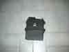
APC control unit
Input: Electric signal from..
- Pressure sensor
- Knock sensor
- RPM
Output: Electric signal to APC valve
Function: Control of the APC system
Mount point: Engine room, right front.
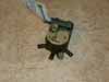
APC valve
Input: Electric signal from APC control unit
Output: Airflow from high-comp side of Turbo to waste gate and low-comp side of
turbo
Function: Controlling the airflow to the waste gate.
Mount point: above radiator
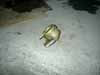
Pressure sensor

Input: Air pressure
Output: Electric signal (ohm)
Function: Feeds the APC control unit with info about the current boost pressure
Mount point: inside cabin, behind the "knee board"
Knock sensor
Input: Mechanic vibration
Output: Electric signal (ohm)
Function: Feeds the APC control unit with info about knock, if any occurs
Mount point: On the engine block below the intake manifold.
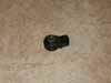
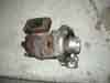
Pressure guard

Picture borrowed with
permission from Jan
Input: Air pressure
Output: Electric signal (ohm)
Function: Cuts the fuel pump if the boost pressure rises over a specific level
Mount point: inside cabin, behind the "knee board"
Turbo
Input: Air pressure
Output: Air pressure
Function: Uses the exhaust from the engine to pump air into the engine
Mount point: Front left side of the engine, mounted on the exhaust manifold.
Waste gate actuator
Input: Air pressure
Output: Mechanical actuation of the valve-valve.
Function: to "bleed" exhaust fumes from the exhaust turbine
wheel in the turbo to lower the speed of the turbine. which leads to lowering of
the boost pressure.
Mount point: On the turbo or right beside it.
Circuit
diagrams
Made by: Anders Olsson
This is unfinished version 0.9 of
the circuit diagrams (current version, not finished)
It's from the old version of APC-box(82-85) grey casing
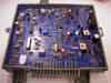

This is version 1.2 of
the circuit diagrams
It's from the new version of APC-box(86-93)
This box is mounted in 900 86-93 and in 9000 86-88, without DI.

Large circuit board
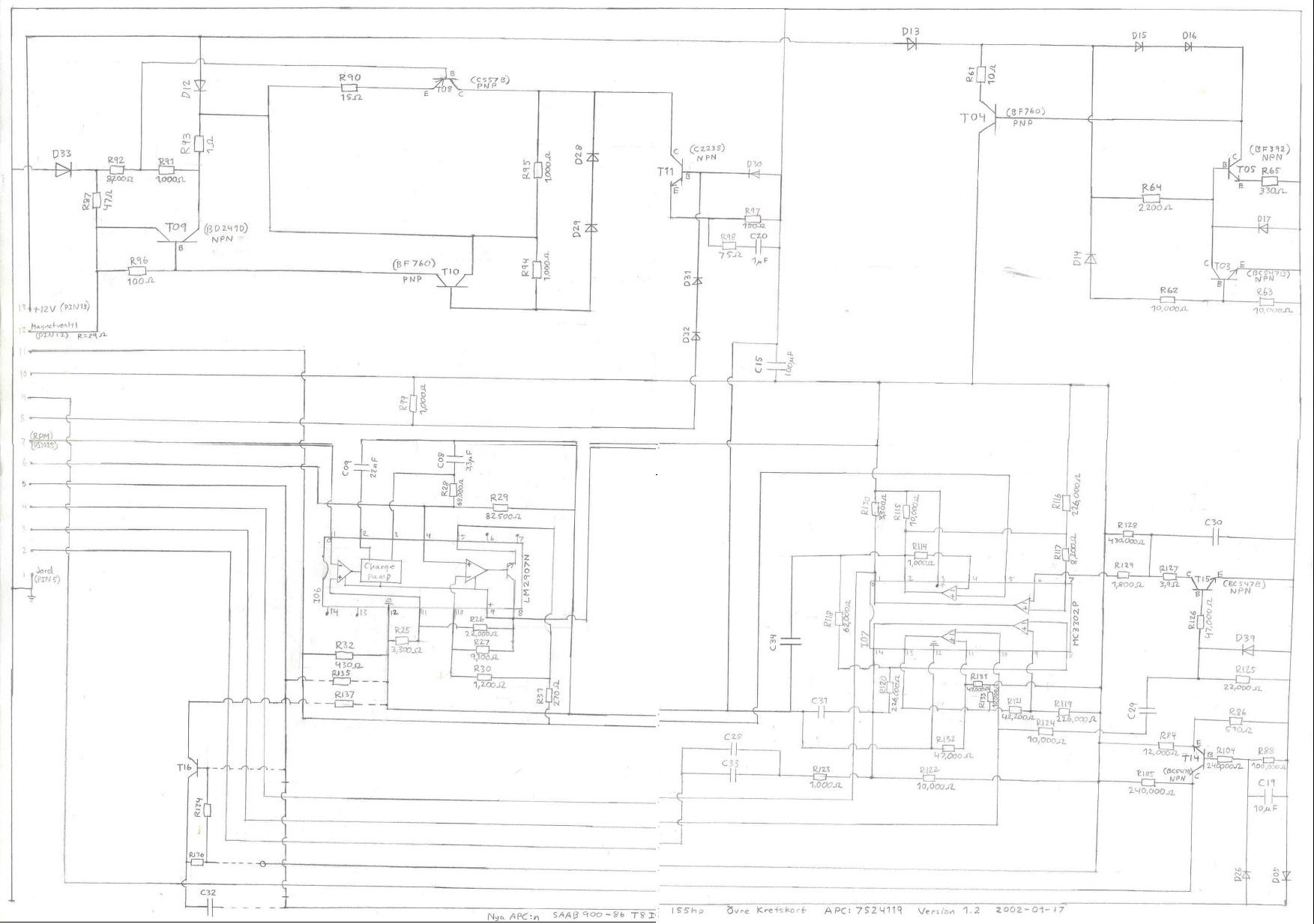
Small circuit board
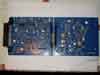
This is version 1.4 of
the circuit diagrams (current version)
It's from the new version of APC-box(86-93)
This box is mounted in 900 86-93 and in 9000 86-88, without DI.

Small circuit board

Large circuit board