-
APC box + wiring (connector at least)
-
Knock sensor
-
Pressure transducer
-
Overpressure switch
-
Solenoid valve
-
Intercooler
-
Length of stainless steel (to make IC bracket)
-
Lower intercooler mounting plate
-
Upper plastic air duct/dam
-
Aluminium pipe (turbo-IC)
-
Aluminium pipe (IC-inlet)
-
Plastic pipe + solenoid valve connector (air box-turbo)
-
Turbo piping flexi hoses + clamps
-
Vacuum piping int. diameter 4 mm and 6 mm
-
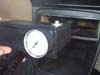
Pressure gauge (Graduated is better for tuning)
-
Various electric cables (different colours &
thicknesses)
-
Electric connectors
-
Insulating tape
-
Remove the centre console (only the part in front of the gear lever)
-
Remove the lower dash fascia
-
Locate the pressure transducer and overpressure switch bracket
-
Remove the bracket and remove the old LPT overpressure switch (this is not the same as the one found on a full pressure turbo)
-
Install the full pressure turbo overpressure switch and the pressure transducer
-
Plug the overpressure switch in the same way as the old one was
-
Prepare 2 wires for the pressure transducer
-
Plug the vacuum/pressure pipe that was on the old overpressure switch into a Y junction to feed air to the pressure transducer and to the new overpressure switch (longer nozzle)
-
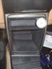
Take a length of pipe from the shorter nozzle on the overpressure switch this shall feed the pressure gauge so adjust the length according to where you will place the gauge (I placed mine in the top section of the centre console)
-
Now take the wiring from the pressure transducer through the bulkhead (I went through one of the rubber grommets just near the brake master cylinder) – make sure it is watertight
-
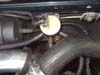
Do the same with a length of wire from the spare plug from the brake switch (this is located just above the brake pedal and is a red wire – be careful as the switch is somewhat fragile)
-
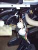
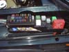
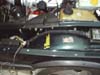
Remove the top of the fuse box
-
Unscrew the to retaining bolts either end of the fuse box
-
Next very carefully peel off the insulating tape of all the wires from the ignition amplifier cable junction to the fuse box (take great care not to cut anything)
-
Cut the original ties on the rubber grommet at the entry of the fuse box (take great care not to damage it)
-
Now you can lift the top half of the fuse box up to access all the wires – if necessary cut any plastic ties so you can manipulate the wires more comfortably
-
First of all bring the wires you previously prepared for the pressure transducer through under the fuse box compartment
-
Take the wires from the APC socket connector and connect the various wires as follows (for 1992 model, older models have different colour codes):
1. Grey/red => connect to APC fuse (10A)
2. Black (thinner) and yellow/red to the wires prepared from the pressure transducer (use cable connectors with
insulation)
3. Blue/red to the blue wire under the TSI socket (funny round 6 pin socket at the front of the fuse box)
4. White to the cable prepared from the brake switch (use cable connectors with insulation)
-
You should now be left with the thick grey wire with the green and the brown wires inside to the knock sensor, a yellow/white to the APC solenoid and the thick black APC ground wire.
-
Now fix the APC box into its location on the inside of the front LH wing and plug the connector in
-
This allows you to position and check the wire lengths so there is no strain on any of them
-
Connect the thick black APC earth wire to the earthing point just opposite the APC box
-
You may also connect the black wire from the solenoid valve at the same place
-
Run the knock sensor wires and the solenoid wires through to their locations to check position and length
-
Now use insulating tape (preferable the textile type as used originally by SAAB) and wrap up all the wiring from the fuse box to the APC box
The next thing is to fit the hardware
-
Remove the air filter housing to give you access to the bottom of the engine compartment and fit the bottom intercooler bracket (the holes are already in the chassis all you need to do is screw the plate on)
-
As you have taken out the air filter housing you can now remove the old plastic pipe between the air box and the turbo and replace with the new one (the new one has the small outlet that is then linked to the APC solenoid - R)
-
Now refit the air filter housing and plug the crankcase vent pipes back to the new piping just fitted previously
Next remove the aluminium pipe from the turbo to the inlet manifold be sure to preserve all the clips and fittings as they might be useful later
-
While the turbo is exposed use a
very clean rag and plug the outlet to prevent ingress of dirt
Now comes a little creative part; trial fit the intercooler and using a length of stainless steel make a small bracket to link the top of the intercooler with the front left radiator mount.
-
You can use a spirit level to get the intercooler straight or just guess (don’t forget that the pipes will have to fit on without fouling with other parts of the car).
-
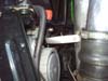
Once you are satisfied with your bracket, fit the intercooler.
-
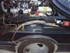
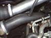
Now you can fit the new aluminium pipes from the turbo to the intercooler and the one from the intercooler to the inlet manifold.
-
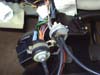
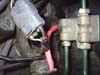
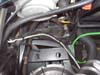
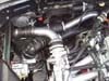
The next to fit is the solenoid valve; you will find two holes in the front crossmember just right of the coil. Fit it here (on mine the holes didn’t line up so I drilled the solenoid valve little bracket rather than the painted body).
Plug the solenoid valve in and connect the vacuum pipes .
1. W – to the wastegate actuator
2. C – to the turbo (compressor side)
3. R – to the plastic pipe with connector (Air box to turbo)
Note on this photo I placed a piece of rubber piping on the aluminium pipe (turbo to IC) to protect it from being damaged by the upper radiator hose and clips where the sensor is.
-
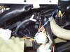
Now last but not least the knock sensor! This is a bugger! Unless you have the engine in bits or the inlet manifold off you will need to place the sensor in its location with your hand either from above or slide you hand under the manifold to the rear of the oil filler cap/pipe then get the bolt and screw it in finger tight then tighten it with a tool but keep the sensor plug in the correct direction (it took me approx. 2 hours to do it with a sore hand at the end)!
-
Plug the sensor in
-
As the final touch fit the plastic air duct to the top of the intercooler